| |
| |
Overview and history |
| |
Equipment designed to be placed in a rack is typically described as rack-mount, rack-mount instrument, a rack mounted system, a rack mount chassis, subrack, rack mountable, or occasionally simply shelf. The height of the electronic modules is also standardized as multiples of 1.75�inches (4.445 �cm) or one rack unit or "U".
Because of their origin as mounting systems for railroad signaling relays, they are still sometimes called relay racks, but the 19-inch rack format has remained a constant while the technology that is mounted within it has changed to completely different fields. The 19-inch (482.6�mm) standard rack arrangement is widely used throughout the telecommunication, computing, audio, entertainment and other industries, though the Western Electric 23-inch standard, with holes on 1-inch (25�mm) centers, prevails in telecommunications.
Nineteen-inch racks are often used to house professional audio and video equipment, including amplifiers, effects units, interfaces, headphone amplifiers, and even small scale audio mixers. They are also widely used for computer server equipment, allowing for dense hardware configurations without occupying excessive floorspace or requiring shelving. A third common use for rack-mounted equipment is industrial power, control, and automation hardware.
Typically, a piece of equipment being installed has a front panel height 1/32-inch (.031") less than the allotted number of Us. Thus, a 1U rackmount computer is not 1.75�inches (44.4�mm) tall but is 1.719�inches (43.7�mm) tall. 2U would be 3.469�inches (88.1�mm) instead of 3.5�inches (88.9�mm). This gap allows a bit of room above and below an installed piece of equipment so it may be removed without binding on the adjacent equipment.
In 1965 a durable fiber reinforced plastic 19-inch rackmount case was patented by ECS Composites and became widely used in military and commercial applications for electronic deployment and operation. State-of-the-art rackmount cases are now also constructed of thermo stamped composite, carbon fiber and DuPont�s Kevlar for demanding military and commercial uses. |
 |
| 19" Rack |
|
|
| |
Equipment mounting |
| |
Fastening |
|
Originally, the mounting holes were tapped to receive a particular type of threaded bolt. This is still frequently used in some government and military applications, often in conjunction with slide rails for ease of maintenance. However, it is no longer typical for frequently changed server racks, due to the possibility for the threads to become damaged or for a bolt to bind and break off, rendering the mounting hole unusable. Tapped-hole racks are still used for hardware that rarely changes, such as phone or network cabling panels and relay racks.
The tapped-hole rack was first replaced by clearance-hole racks. The holes are large enough to permit a bolt to be freely inserted through without binding, and bolts are fastened in place using cage nuts. A cage nut consists of a spring steel cage, designed to clip onto the open mounting hole, within which is a captive nut. In the event of a nut being stripped out or a bolt breaking, the nut can be easily removed and replaced with a new one. Production of clearance-hole racks is less expensive because tapping the holes is eliminated and replaced with fewer, less expensive, cage nuts.
The next innovation in rack design has been the square-hole rack. Square-hole racks allow boltless mounting, such that the rack-mount equipment only needs to insert through and hook down into the lip of the square hole. Installation and removal of hardware in a square hole rack is very easy and boltless, where the weight of the equipment and small retention clips are all that is necessary to hold the equipment in place. Older equipment meant for round-hole or tapped-hole racks can still be used, with the use of cage nuts made for square-hole racks.
Structural support
Rack-mountable equipment is mounted by bolting or clipping its front panel to the rack. One weakness of this system is that all the structural support is at one edge of the equipment, so heavier equipment is designed to use a second pair of mounting posts located at the back of the equipment. Various spacings between the front and rear posts are used; 31.5�inches (800�mm) is typical, and equipment is often designed to handle a range of rack depths. Depth of 39.4�inches (1,000�mm) is becoming increasingly common; more depth allows for more space to route cables at the back.
The strength required of the mounting posts means they are invariably not merely flat strips but actually a wider folded strip arranged around the corner of the rack. The posts are usually made of steel of around 2�mm thickness (the official standard recommends a minimum of 1.9�mm), or of slightly thicker aluminum.
Racks, especially two-post racks, are often secured to the floor or adjacent building structure so as not to fall over. This is usually required by local building codes in seismic zones. According to Telcordia Technologies Generic Requirements document GR-63-CORE, during an earthquake, telecommunications equipment is subjected to motions that can over-stress equipment framework, circuit boards, and connectors. The amount of motion and resulting stress depends on the structural characteristics of the building and framework in which the equipment is contained, and the severity of the earthquake. Seismic racks rated according to Telcordia GR-63-CORE are available,with Zone 4 representing the most demanding environment. Telcordia GR-3108-CORE specifies the usable opening of seismic-compliant 19-inch racks.
|
 |
| A typical section of 19-inch (482.6�mm) server rack rail |
|
|
| |
Rails (slides) |
|
Heavy equipment or equipment which is commonly accessed for servicing, for which attaching or detaching at all four corners simultaneously would pose a problem, is often not mounted directly onto the rack but instead is mounted via rails (or slides). A pair of rails is mounted directly onto the rack, and the equipment then slides into the rack along the rails, which support it. When in place, the equipment may also then be bolted to the rack. The rails may also be able to fully support the equipment in a position where it has been slid clear of the rack; this is useful for inspection or maintenance of equipment which will then be slid back into the rack.
Slides or rails for computers and other data processing equipment such as disk arrays or routers often need to be purchased directly from the equipment manufacturer, as there is no standardization on such equipment's thickness (measurement from the side of the rack to the equipment) or means for mounting to the rail. |
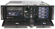 |
| 3U rackmount system |
|
|
| |
Computer mounting |
|
Computer servers designed for rack-mounting can include a number of extra features to make the server easy to use in the rack:
- The sliding rails can lock in various extended positions to prevent the equipment from moving when extended out from the rack for service.
- The server itself might have locking pins on the sides that just drop into slots on the extended rail assembly, in a manner similar to a removable kitchen drawer. This permits a very easy server installation and removal since there is no need for the server to be held in midair while someone fastens each rail to the sides of the server with screws.
- Some manufacturers of rack-mount hardware include a folding cable tray behind the server, so that the cables are held into a neat and tidy folded channel when inside the rack, but can unfold out into a long strip when pulled out of the rack, allowing the server to continue to be plugged in and operating normally even while fully extended and hanging in midair in front of the rack. This piece of equipment thus simplifies maintenance, but at the cost of providing a restriction to airflow.
- Rack-optimized servers might duplicate indicator lights on the front and rear of the rack to help identify a machine needing attention, or provide a separate "identify" LED indicators on both sides of the server (which can be turned on in software or by pushing an associated button). Since some configurations permit over fifty 1U servers in a single rack, this provides a simple method to determine exactly which machine is having a problem when at the rear of the rack.
- A handle may be provided at the rear of the server rails, to help pull or push the server without having to pull on the cables.
When there are a large number of computers in a single rack, it is impractical for each one to have its own separate keyboard, mouse, and monitor. Instead, a KVM switch or LOM software is used to share a single keyboard/video/mouse set amongst many different computers.
Since the mounting hole arrangement is vertically symmetric, it is possible to mount rack-mountable equipment upside-down. However, not all equipment is suitable for this type of mounting. For instance, most optical disc players will not work upside-down because the driving motor mechanism does not grip the disc. |
| |
Four- and two-post racks |
|
| Racks are available with either four or two vertical posts. Four-post racks allow for mounting rails to support the equipment at the front and rear. These racks may be open in construction (similar to the traditional open-style two-post racks), or may be enclosed by front and/or rear doors, side panels, or tops. Two-post racks provide just two vertical posts; a piece of equipment can be mounted either via its front panel holes, or close to its center of gravity (to minimize load on its front panel), depending on the design of the rack. Two-post racks are most often used for telecommunication installations. |
| |
Specifications |
| |
The formal standards for a 19-inch (482.6�mm) rack are available from the following:
- Electronic Industries Alliance EIA-310-D, Cabinets, Racks, Panels, and Associated Equipment, dated September, 1992. (Latest Standard Now REV E 1996)
- Consumer Electronics Association CEA-310-E design requirements for Cabinets, Panels, Racks and Subracks., dated December 14, 2005
- International Electrotechnical Commission Multiple documents in available in French and English versions.
- IEC 60297 Mechanical structures for electronic equipment - Dimensions of mechanical structures of the 482,6�mm (19�in) series
- IEC 60297-1 Replaced by IEC 60297-3-100
- IEC 60297-2 Replaced by IEC 60297-3-100
- IEC 60297-3-100 Part 3-100: Basic dimensions of front panels, subracks, chassis, racks and cabinets
- IEC 60297-3-101 Part 3-101: Subracks and associated plug-in units
- IEC 60297-3-102 Part 3-102: Injector/extractor handle
- IEC 60297-3-102 Part 3-103: Keying and alignment pin
- IEC 60297-3-104 Part 3-104: Connector dependent interface dimensions of subracks and plug-in units
- IEC 60297-3-105 Part 3-105: Dimensions and design aspects for 1U chassis
- IEC 60297-4 Replaced by IEC 60297-3-102
- IEC 60297-5 Multiple documents, -100, 101, 102, ... 107, replaced by IEC 60297-3-101
- Deutsches Institut f�r Normung DIN 41494 - Multiple documents in German but some documents are available in English.
- DIN 41494 Equipment practices for electronic equipment; mechanical structures of the 482,6�mm (19�inch) series
- DIN 41494-7 Dimensions of cabinets and suites of racks.
- DIN 41494-8 Components on front panels; mounting conditions, dimensions
- DIN IEC 60297-3-100 (see above in IEC section)
|
 |
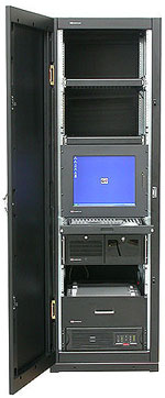
| Rack-width sliding keyboard & monitor with equipment mounted in a rack |
|
|
A rack's mounting fixture consists of two parallel metal strips (also referred to as "posts" or "panel mounts") standing vertically. The posts are each 0.625�inches (15.875�mm) wide, and are separated by a gap of 17.75�inches (451�mm), giving an overall rack width of 19�inches (482.6�mm). The posts have holes in them at regular intervals, with both posts matching, so that each hole is part of a horizontal pair with a center-to-center distance of 18.375�inches (467�mm).
The holes in the posts are arranged vertically in repeating sets of three, with center-to-center separations of 0.5�inches (12.7�mm), 0.625�inches (15.9�mm), 0.625�inches (15.9�mm). The hole pattern thus repeats every 1.75�inches (44.45�mm). Racks are divided into regions, 1.75�inches (44.45�mm) in height, within which there are three complete hole pairs in a vertically symmetric pattern, the holes being centered 0.25�inches (6.4�mm), 0.875�inches (22.2�mm), and 1.5�inches (38.1�mm) from the top or bottom of the region. Such a region is commonly known as a "U", for "unit", and heights within racks are measured by this unit. Rack-mountable equipment is usually designed to occupy some integer number of U. For example, an oscilloscope might be 4U high, and rack-mountable computers are most often 1U or 2U high. A blade server enclosure might require 10U. Occasionally, one may see fractional U devices such as a 1.5U server, but these are much less common.
The height of a rack can vary from a few inches, such as in a broadcast console, to a floor mounted rack whose interior is 78.75�inches (200.0�cm) (45 rack units) high. Many wall-mounted industrial equipment enclosures have 19-inch rack rails to support mounting of equipment. |

